What Is an Impressed Current Anode?
An Impressed Current Anode is a key component in an impressed current cathodic protection system. It helps protect buried pipelines, ship hulls, storage tanks, and other metal structures from corrosion. Unlike a sacrificial anode, it works with an external direct-current power source. The anode discharges protective current into the surrounding soil, water, or other electrolyte, reducing corrosion on the structure’s surface.
It is not magic. The system’s performance depends on correct design, installation, and monitoring. Anodes may use materials such as mixed-metal-oxide-coated titanium or high-silicon cast iron, selected to suit the environment and operating conditions. On site, details matter: soil resistivity, moisture, coating condition, anode placement, and electrical connections can all affect current distribution. Poor placement may leave some areas underprotected while increasing demand elsewhere.
This guide explains what an Impressed Current Anode does, how it differs from a sacrificial anode, and where common materials are used. It also introduces practical considerations for system selection and maintenance. Actual designs should be assessed by qualified corrosion professionals using project-specific measurements and applicable technical guidance. A simple definition is useful, but it cannot replace field data.
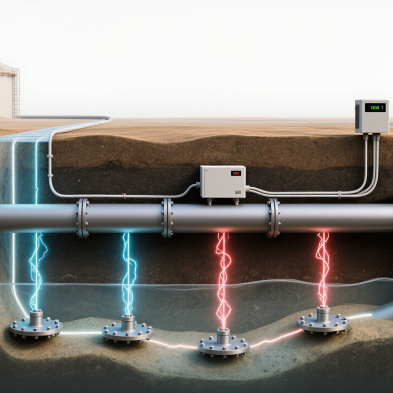
Definition and DC Operating Principle of Impressed-Current Anodes
An impressed-current anode is the positive electrode in a cathodic protection system. A DC power source, often a rectifier, supplies current to it. The anode releases current into soil or water, which carries it to the metal structure being protected. That structure connects to the power source’s negative terminal and acts as the cathode. The adjusted electrical potential helps reduce corrosion.
Unlike a sacrificial anode, an impressed-current anode relies on an external power supply rather than its own natural potential to drive protective current. Some anode materials are consumed slowly; others are designed for long service, but none should be treated as maintenance-free. Current output depends on factors such as electrolyte resistance, anode placement, and the structure’s coating condition. Field conditions rarely match a clean diagram exactly. That is worth remembering when interpreting readings.
Tips: Check anode connections, power output, and structure-to-electrolyte potential at regular intervals. A sudden change may point to a loose cable, damaged coating, or altered soil conditions. Use measurements, not appearance alone.
What Is an Impressed Current Anode? - Definition and DC Operating Principle of Impressed-Current Anodes
| Dimension | Description | Practical significance |
| Definition | An impressed-current anode is the positive electrode in a cathodic protection system. It discharges direct current into an electrolyte, such as soil or water, to help protect a connected metal structure from corrosion. | It is part of an externally powered system; the anode itself is not the protected structure. |
| DC power connection | The anode is connected to the positive terminal of a DC power source, commonly a transformer-rectifier. The protected structure is connected to the negative terminal. | Correct polarity is essential. Incorrect wiring can accelerate corrosion of the structure. |
| Current path | Conventional current flows from the anode, through the electrolyte, to the protected structure. The electrical circuit is completed through the external wiring and DC source. | Electrolyte contact and electrical continuity are required for the protection circuit to operate. |
| Protected structure | The structure becomes the cathode. Electrons supplied through the negative connection support cathodic reactions at its surface, reducing the tendency for iron to dissolve as corrosion products. | Protection depends on distributing adequate current over the structure while avoiding excessive polarization. |
| Anode reaction | Oxidation occurs at the anode. In aqueous environments, a common reaction is water oxidation that produces oxygen; the exact reaction depends on the anode material and electrolyte chemistry. | Anode material and operating conditions affect consumption, service life, and the environment around the anode. |
| Common anode materials | Examples include mixed-metal-oxide-coated titanium, high-silicon cast iron, and graphite. Material selection depends on the electrolyte, required current output, installation, and design criteria. | These materials are selected for their behavior in particular service conditions; they are not interchangeable in every application. |
| Typical applications | Impressed-current cathodic protection is used for structures such as buried pipelines, storage tanks, marine structures, and reinforced concrete. | The anode arrangement and electrical settings are designed for the structure and its surrounding environment. |
| Control and monitoring | System output can be adjusted at the DC power source. Operation is commonly checked by measuring structure-to-electrolyte potentials and other relevant electrical parameters. | Regular monitoring helps confirm protection criteria and identify changes in system performance. |
| Key design factors | Design considers electrolyte resistivity, structure size and coating condition, current demand, anode distribution, cable connections, and the required service life. | There is no single universal current setting; qualified design and field measurements are important. |
| Difference from a sacrificial anode | An impressed-current system uses an external DC power source. A sacrificial-anode system relies on the natural potential difference between the anode material and the protected metal. | Impressed-current systems allow adjustable output but require power, electrical connections, and ongoing checks. |
Note: Actual reactions, current requirements, anode life, and protection criteria vary with the material, electrolyte, structure, and applicable engineering standards.
Anode Materials: MMO-Coated Titanium, High-Silicon Iron, and Graphite
What Is an Impressed Current Anode?
In an impressed-current cathodic protection system, an external power source drives current from an anode through soil or water to a metal structure. The anode does not protect the structure by itself. Performance also depends on current demand, electrolyte conditions, cable connections, and installation quality. Material choice affects service life, output, and maintenance. Small details matter.
MMO-coated titanium has a mixed-metal-oxide layer on a titanium substrate. It can discharge current efficiently and is used in soil, water, and concrete applications. But coating damage, unsuitable current density, or poor bedding may shorten service life.
High-silicon cast iron is robust and often installed in buried systems with conductive coke backfill. Its weight can make handling harder. Not always convenient.
Graphite offers good conductivity and relatively low material cost. However, it is brittle; careless transport or installation can cause cracks, so the anode and connections need inspection.
There is no universal winner. Selection should account for soil resistivity, required output, design life, and anode spacing, supported by project measurements and technical data. Actual soil conditions may differ from survey results, so reviewing performance after installation is worthwhile, even when calculations looked sound.
Pipeline Protection Criteria: −850 mV CSE or 100 mV Shift (AMPP SP0169)
What Is an Impressed Current Anode?
For a buried steel pipeline, an impressed current anode delivers protective current from an external power source. The anode sits in a groundbed; the rectifier’s positive lead connects to it, while the negative lead connects to the pipeline. Current then flows through the soil toward the pipe. The goal is to reduce corrosion, not simply to produce a dramatic voltage reading.
AMPP SP0169 commonly describes two protection criteria: a polarized potential of −850 mV or more negative versus a copper/copper sulfate reference electrode (CSE), or a polarization shift of at least 100 mV. These are alternative criteria, not numbers to combine. Measurements matter. A technician may use an instant-off reading to reduce voltage error caused by current flowing through soil. Reference-electrode placement also affects the result. Small details count.
The 100 mV shift criterion tracks polarization from an established baseline, which can be useful when the −850 mV criterion is difficult to apply. Yet neither value should be treated as a universal pass stamp. Coating condition, stray current, soil conditions, and measurement quality can change the interpretation. In the field, a loose test lead or poorly positioned CSE can distort a reading. That part is easy to underestimate. Engineers should document the method, confirm stable readings, and investigate unusual trends before adjusting rectifier output.
What Is an Impressed Current Anode?
Pipeline Protection Criteria: −850 mV CSE or 100 mV Shift (AMPP SP0169)
An impressed current anode delivers protective current from an external DC source to the pipeline. The example readings are illustrative: readings more negative than −850 mV CSE meet the plotted potential criterion; the −790 mV reading does not. Where applicable, AMPP SP0169 also recognizes at least 100 mV of cathodic polarization. Assess criteria using appropriate measurements and consideration of voltage drops.
System Design: Rectifiers, Groundbeds, Cables, and Current Distribution
An impressed current anode is one part of a cathodic protection system. It releases direct current into soil or water, helping reduce corrosion on a connected metal structure. A rectifier supplies that current: its positive lead connects to the anode circuit, while its negative lead connects to the structure. Polarity matters. A reversed connection can undermine protection rather than improve it.
Groundbed design shapes how current reaches the structure. Anodes may sit in a shallow bed or a deep well, depending on site conditions, available space, and soil resistivity. Cables must withstand the environment, carry the expected current, and have sound insulation where they pass through soil or water. Even a small damaged section can create trouble. Small details matter.
Current distribution is not automatic. Anode spacing, structure geometry, coating condition, and changes in soil resistivity all affect where current flows. Engineers use calculations to estimate output, then check actual conditions with field measurements, such as structure-to-electrolyte potentials. I have seen designs look tidy on paper yet need adjustment after commissioning; models cannot capture every site detail. Rectifier settings should therefore be reviewed against measurements, not guessed from a single reading. A useful design leaves room for inspection, cable testing, and practical adjustment over time.
Installation and Performance Testing Under ISO 15589-1 and AMPP SP0169
What Is an Impressed Current Anode?
Under ISO 15589-1 and AMPP SP0169, an impressed current anode is part of a designed cathodic protection system—not a standalone fix. Installation begins with soil resistivity, coating condition, and current-demand assessment. Anodes are positioned in prepared groundbeds, commonly surrounded by conductive carbonaceous backfill. Cable connections need sound insulation and continuity; one weak joint can distort the readings. Rectifier output is then adjusted against field measurements, not guesswork.
Commissioning should record structure-to-electrolyte potentials using a calibrated reference electrode, rectifier voltage and current, and relevant electrical continuity or isolation checks. Where interruption testing is used, synchronized switching helps separate IR drop from polarized potential. Acceptance criteria should follow the applicable standard and project design; a single “on” reading may be misleading. NACE International’s IMPACT study, published in 2016 using 2013 estimates, placed global corrosion costs at US$2.5 trillion annually, or 3.4% of global GDP. That figure covers corrosion broadly, but it shows why documented testing matters.
Tips: Photograph each groundbed and cable joint before backfilling. Keep baseline readings, electrode locations, and rectifier settings together. Small details matter. Then repeat measurements under comparable conditions; seasonal soil changes can shift results. The awkward part: a neat commissioning sheet cannot prove every buried connection will remain sound. Schedule follow-up surveys and investigate unexplained current or potential changes.