Blog
What Is a Compact Transformer Substation?
As electricity demand rises, the grid needs equipment that is powerful, space-efficient, and easier to deploy. The International Energy Agency’s Electricity 2024 report forecasts global electricity demand growth of about 4% annually through 2026. Meanwhile, IRENA recorded 473 gigawatts of new renewable capacity in 2023. These additions create more pressure on local distribution networks, especially near factories, data centers, housing projects, and solar parks.
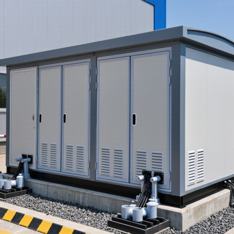
A Compact Transformer Substation combines a transformer, medium-voltage switchgear, protection devices, and low-voltage connections inside a confined footprint. Picture a weatherproof enclosure beside a factory gate, converting incoming voltage while keeping cables, barriers, and controls organized. Leonard L. Grigsby, editor of The Electric Power Engineering Handbook, describes the substation as “the vital link between generation, transmission, and distribution.” That link is becoming more valuable as power flows grow less predictable.
The benefits appear practical: reduced land use, shorter installation periods, improved operator safety, and lower cable losses when equipment sits near demand. Yet compact design is not automatically better. Heat dissipation, fault clearance, ventilation, noise, maintenance access, and flood protection still require careful engineering. This is where project experience matters. A small enclosure can hide a large risk.
This guide examines Compact Transformer Substation design, components, applications, standards, and lifecycle considerations. It also questions common assumptions, because the cheapest installation may not deliver the lowest lifetime cost.
Definition and Purpose of a Compact Transformer Substation
What Is a Compact Transformer Substation?
Definition and Purpose of a Compact Transformer Substation
A compact transformer substation is a factory-assembled electrical unit that combines medium-voltage equipment, a transformer, and low-voltage distribution panels. Its enclosed design reduces installation space and protects essential components from dust, moisture, and accidental contact. In practical projects, engineers often select these substations for residential developments, factories, commercial buildings, and renewable energy sites.
The transformer changes incoming medium voltage into a safer, usable voltage for local equipment. Switchgear controls the electrical supply and isolates faults during maintenance. Low-voltage panels then distribute power through outgoing circuits. A properly designed unit may also include cooling features, earthing connections, metering, and protective relays. Every component has a specific job.
Placement matters greatly. Field teams must check ventilation, drainage, cable access, fire separation, and working clearance before installation. A narrow enclosure may save valuable space, but it can complicate inspection or future repairs. This is where design assumptions sometimes fail. A substation that fits the site may still perform poorly if heat cannot escape.
Reliable operation depends on correct load calculations, coordination between protective devices, and routine inspection. Technicians should examine connections for overheating, listen for unusual transformer noise, and verify insulation condition. Local electrical codes and utility requirements also influence the final design. Compact does not mean maintenance-free. It means essential functions are arranged efficiently within a controlled footprint.
Main Components and Their Functions
A compact transformer substation combines medium-voltage equipment, a transformer, and low-voltage distribution gear in one protected enclosure. Its transformer reduces incoming voltage for factories, buildings, or local networks. The enclosure controls access, weather exposure, and internal clearances. Ventilation openings or cooling fins help release heat during heavy loads. Small mistakes matter here.
Medium-voltage switchgear controls incoming power and isolates faults. Fuses, circuit breakers, and relays protect the transformer from short circuits and overloads. The transformer core and windings perform the voltage conversion. On the output side, a low-voltage panel distributes electricity through outgoing feeders. Cable terminations, bushings, and busbars provide secure electrical connections. An earthing system directs fault current safely into the ground. Some units include temperature indicators, pressure relief devices, and digital monitoring. These features support safer maintenance and faster fault inspection. However, protection settings must match the actual network, not a convenient default.
Tips: Keep the substation accessible for inspection and emergency isolation. Check cable joints for heat marks, moisture, or unusual odors. Confirm that ventilation paths remain clear. Use tested instruments and follow local electrical codes. A neat enclosure can still conceal a loose connection. Review drawings after every modification. In practice, records are often incomplete, so verify labels directly against the installed equipment before energizing.
How a Compact Transformer Substation Operates
What Is a Compact Transformer Substation?
How a Compact Transformer Substation Operates
A compact transformer substation receives medium-voltage electricity through an incoming switch. The switch isolates faults and allows technicians to work safely. Protection relays monitor current, voltage, and abnormal temperature. When conditions become dangerous, the circuit breaker opens within milliseconds.
The transformer then reduces voltage for local distribution. Inside, copper windings transfer energy through a magnetic field. The low-voltage panel sends power to buildings, workshops, or nearby infrastructure. Cable compartments keep connections enclosed, while ventilation or liquid cooling removes heat. This arrangement uses limited space without removing essential protection.
The International Energy Agency’s Electricity Grids and Secure Energy Transitions report estimates that 80 million kilometres of grids require replacement or new construction by 2040. Its investment outlook also exceeds 600 billion dollars annually. These figures explain why compact substations matter in dense areas and expanding networks. The IEA’s Electricity 2024 report also projects strong global electricity-demand growth through 2026, increasing pressure on local distribution equipment.
Field experience shows that operation depends on more than nameplate capacity. Dust, moisture, uneven loading, and poor cable termination can reduce reliability. A substation may pass factory tests and still perform poorly after installation. Regular infrared scans, relay testing, oil or insulation checks, and torque inspections remain important. IEC 62271 requirements guide high-voltage switchgear design, but site conditions still demand engineering judgement. That judgement is sometimes imperfect.
Common Types and Installation Configurations
What Is a Compact Transformer Substation?
Common Types and Installation Configurations
A compact transformer substation combines medium-voltage switching, a transformer, and low-voltage distribution equipment in one enclosure. Its sealed structure saves space and reduces exposure to dust, rain, and accidental contact. Common types include kiosk substations, indoor units, underground units, and outdoor ground-mounted designs. Kiosk units suit factories, offices, and residential developments. Underground configurations preserve public space, but they require reliable drainage and careful access planning. Indoor units offer better environmental control, although rooms need fire protection, ventilation, and sufficient working clearance.
Installation configuration depends on load demand, site conditions, and future expansion. A radial arrangement is simple and economical for smaller facilities. Ring-main configurations improve supply continuity when one cable section needs maintenance. Dual-transformer layouts support larger loads and planned redundancy. Engineers should check transformer capacity, cable routes, earthing, noise, ventilation, and protection settings together. A neat drawing can still hide difficult maintenance access. Field inspections often reveal this problem.
Tips: Leave clear space around doors and cable compartments. Confirm flood levels before selecting an underground location. Keep high-voltage and low-voltage sections physically separated. Use tested lifting points during placement. Review the layout with operators, not only designers. Small oversights matter. A practical inspection plan should include temperature checks, connection tightening, insulation testing, and protection verification. Local electrical codes and utility requirements must guide the final design.
Key Benefits, Applications, and Maintenance Needs
What Is a Compact Transformer Substation?
Key Benefits, Applications, and Maintenance Needs
A compact transformer substation combines medium-voltage switching, a transformer, and low-voltage distribution equipment in one enclosed unit. Its smaller footprint suits factories, commercial buildings, solar farms, and urban developments with limited space. The International Energy Agency reported that global electricity demand could grow by about 4% annually through 2026. This pressure makes efficient local distribution increasingly valuable. Compact substations can reduce cable runs, simplify installation, and limit visual impact. They also support renewable projects. IRENA reported 473 GW of renewable capacity added worldwide in 2023, creating more demand for flexible grid connection equipment. Faster installation is useful. It is not always cheaper.
Maintenance requires disciplined field practice. Technicians should inspect enclosure seals, ventilation paths, cable terminations, earthing connections, and visible corrosion. Infrared scanning can reveal abnormal heating before failure becomes obvious. Oil-filled units may require sampling, moisture checks, and dissolved-gas analysis. Dry-type transformers still need cleaning and thermal inspection. NETA maintenance guidance recommends documented testing, safe isolation, and condition-based intervals rather than relying only on calendar dates. That approach is more realistic, though many sites still postpone inspections until alarms appear. A blocked vent, loose termination, or aging gasket can turn a compact design into a difficult repair. Access planning matters. Spare fuses, test records, and clear switching labels should remain available. Small equipment still needs serious attention.
What Is a Compact Transformer Substation? - Key Benefits, Applications, and Maintenance Needs
| Data Dimension | Typical Information | Why It Matters | Maintenance or Design Note |
|---|---|---|---|
| Definition | A factory-assembled, enclosed substation that integrates medium-voltage switching, a distribution transformer, and low-voltage distribution equipment in one compact housing. | It reduces installation complexity and provides a coordinated, space-efficient power distribution unit. | The complete assembly should be selected, installed, and tested as a coordinated system rather than as unrelated components. |
| Main Sections | Usually includes a medium-voltage compartment, transformer compartment, and low-voltage compartment. | Physical separation improves safety, simplifies cable routing, and supports easier access for inspection. | Access doors, barriers, interlocks, and cable compartments must remain correctly installed and functional. |
| Primary Voltage | Common medium-voltage primary systems are in the approximately 6 kV to 36 kV range, depending on the utility or facility network. | The primary voltage determines insulation requirements, switchgear selection, clearances, and protection settings. | Verify rated voltage, power-frequency withstand, impulse withstand, and local electrical-code requirements before installation. |
| Secondary Voltage | Low-voltage outputs commonly include 400/230 V or 480/277 V systems, depending on regional practice and the connected load. | The secondary voltage must match motors, lighting, control systems, and other downstream equipment. | Check phase sequence, neutral configuration, earthing arrangement, and compatibility with connected loads. |
| Transformer Type | May use an oil-immersed transformer or a dry-type transformer. Dry-type units are often preferred indoors or where reduced liquid-fire risk is important. | The transformer type affects fire protection, ventilation, environmental requirements, noise, and maintenance practices. | Oil-filled units require checks for leaks, oil condition, pressure devices, and liquid level; dry-type units require cleaning and thermal inspection. |
| Typical Power Rating | Distribution transformer ratings commonly range from tens of kVA to several MVA. The correct rating depends on maximum demand, diversity, motor starting, and future expansion. | Correct sizing limits overheating, voltage drop, unnecessary losses, and premature insulation aging. | Review load growth and transformer loading. Sustained overloads can shorten insulation life and increase operating temperature. |
| Enclosure and Protection | Outdoor compact substations generally use a weather-resistant metal or concrete enclosure with a defined ingress-protection rating. | The enclosure protects energized equipment from dust, moisture, accidental contact, and environmental exposure. | Inspect seals, roof joints, corrosion, ventilation openings, locks, drainage, and the enclosure’s protection rating. |
| Space Requirement | The footprint is generally smaller than that of separately installed switchgear, transformer, and low-voltage panels, but exact dimensions depend on rating and layout. | A reduced footprint is useful in urban sites, factories, renewable-energy facilities, and restricted utility compounds. | Maintain required working clearances, access routes, ventilation space, lifting points, and emergency escape paths. |
| Key Benefits | Compact layout, faster site installation, reduced interconnection work, improved equipment protection, and simplified civil construction. | Factory assembly can reduce on-site wiring errors and shorten project schedules when the design is properly coordinated. | Benefits depend on correct transport, foundation preparation, cable termination, commissioning, and protection coordination. |
| Typical Applications | Industrial plants, commercial buildings, residential developments, data facilities, construction sites, transport infrastructure, solar plants, and wind farms. | The integrated format supports reliable power distribution where space, installation time, or environmental protection is important. | Application-specific requirements may include arc-flash mitigation, seismic design, coastal corrosion protection, or low-noise operation. |
| Protection Functions | Typical functions include overcurrent, short-circuit, earth-fault, transformer temperature, and low-voltage circuit protection. | Proper protection limits equipment damage and helps isolate faults while maintaining service to unaffected circuits. | Protection settings should be coordinated with upstream and downstream devices and verified through commissioning tests. |
| Routine Visual Inspection | Check for abnormal noise, odor, vibration, overheating, water ingress, dust accumulation, corrosion, loose covers, and warning-label damage. | Early detection can prevent minor defects from developing into insulation failure, fire, or unplanned outage. | Inspection frequency should be risk-based; many facilities perform routine checks monthly or quarterly, subject to site conditions. |
| Electrical Testing | Testing may include insulation resistance, winding resistance, transformer ratio, grounding continuity, breaker operation, relay function, and cable tests. | Testing confirms that insulation, switching, protection, and earthing systems remain suitable for service. | Perform tests during commissioning, after major modifications, and at intervals defined by the manufacturer, regulations, and maintenance program. |
| Thermal Monitoring | Infrared thermography can identify hot connections, overloaded conductors, poor contact pressure, and uneven phase loading while equipment is energized. | Abnormal temperature patterns often provide an early indication of connection or loading problems. | Thermal surveys should be conducted by qualified personnel under suitable load conditions and followed by de-energized corrective work. |
| Cleaning and Ventilation | Remove dust and debris, keep ventilation paths clear, and ensure cooling fans, filters, and thermostats operate correctly where fitted. | Clean and unobstructed cooling paths help control temperature and reduce contamination-related tracking. | Never clean energized high-voltage equipment. Use approved procedures and avoid compressed air that may drive contaminants into insulation. |
| Grounding and Bonding | The enclosure, transformer tank or core frame, cable screens, switchgear, and supporting steelwork should be bonded to the site grounding system. | Effective grounding helps control touch voltage and provides a path for fault current so protective devices can operate. | Inspect connections for corrosion and looseness, and measure grounding-system performance according to local requirements. |
| Safety Requirements | Use qualified electrical personnel, isolation and lockout/tagout procedures, voltage verification, appropriate personal protective equipment, and controlled access. | Compact equipment contains hazardous voltages and may present arc-flash, electric-shock, fire, and stored-energy risks. | Follow applicable electrical-safety regulations, risk assessments, operating instructions, and emergency-response procedures. |
| Relevant Standards | Commonly referenced standards include IEC 62271-202 for high-voltage/low-voltage prefabricated substations and IEC 60076 for power transformers, together with applicable national codes. | Standards define requirements for design verification, insulation, temperature rise, enclosure performance, testing, and safety. | The applicable edition and local regulations should be confirmed for each project before procurement and commissioning. |

Note: Voltage levels, transformer ratings, enclosure ratings, and maintenance intervals vary by project, installation environment, applicable regulations, and the equipment manufacturer’s instructions.