
Blog
What Are the Top 10 Power Supply Connector Types?
Choosing the right connector can prevent heat buildup, loose contacts, and unexpected equipment downtime. Power Supply Connectors may look small, but each one controls how safely energy reaches a device. Their shape, pin layout, current rating, and locking method all matter.
This guide examines ten widely used connector types across computers, industrial controls, LED systems, appliances, and electronic equipment. It considers practical factors, including voltage compatibility, contact durability, installation space, and service access. Examples include the familiar barrel connector, IEC appliance inlet, Molex-style connector, USB power connector, and DC terminal block.
The list is based on manufacturer datasheets, established engineering practices, and common field applications. Safety remains essential. A connector should match the cable, insulation, load, and operating environment. A connector that fits physically may still be electrically unsuitable.
Fit is not enough.
Real-world selection is rarely perfect. A compact connector may save space but tolerate less current. A locking design can improve reliability but slow maintenance. Some product names also describe several variations, which can create confusion between manufacturers. That limitation deserves attention.
You will see where each connector performs well, where it needs caution, and which specifications deserve closer inspection. The goal is not to declare one universal winner. Instead, this overview offers a practical way to compare connector types before purchasing, designing, or replacing a power connection. Clear choices begin with accurate ratings and honest evaluation.
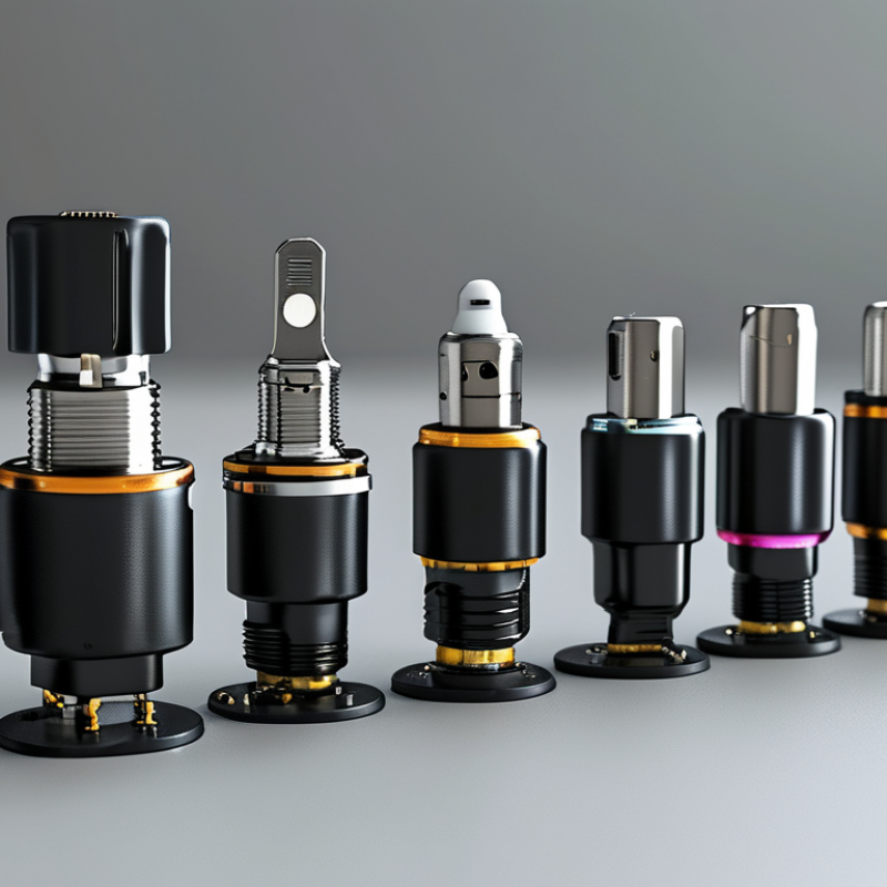
Understanding Power Supply Connectors and Their Core Functions
Power supply connectors transfer electrical energy safely between a source and a device. Their shape, voltage rating, current capacity, and locking method determine how well they perform. The ten common types include barrel, USB, DC coaxial, terminal block, Molex-style peripheral, SATA power, ATX, EPS, PCIe, and IEC connectors. Each serves a different purpose. A barrel connector often powers compact electronics, while USB connectors support low-voltage devices and charging. ATX and EPS connectors distribute stable power across computer boards and processors.
Connector design affects more than compatibility. A SATA power connector supplies drives through separate voltage rails, while a PCIe connector delivers higher current to expansion hardware. Terminal blocks support field wiring and easier maintenance. IEC connectors commonly connect equipment to external power cords. Secure locking reduces accidental disconnection. Correct polarity matters. Always check it.
In practical inspection, I look for loose pins, darkened plastic, bent contacts, and cable strain. Heat tells a story. Excessive warmth may indicate overload, poor contact, or undersized wiring. A connector can look correct and still fail under load. That is an easy mistake to make. I also verify voltage, current, wire gauge, and mating dimensions before installation. Datasheets remain essential because similar-looking connectors may use different pin assignments. Fit matters. When uncertain, controlled testing with proper measurement equipment is safer than forcing a connection.
How Power Supply Connectors Are Classified by Design and Application
What Are the Top 10 Power Supply Connector Types?
How Power Supply Connectors Are Classified by Design and Application
Power supply connectors are classified by contact design, current capacity, voltage, and installation environment. A DC barrel connector suits compact adapters and small devices. A coaxial power connector provides a stable connection for equipment needing controlled polarity. USB-C power connectors support compact electronics and negotiated power delivery. Terminal blocks use screw or spring contacts for panels, control cabinets, and field wiring. They are practical, but loose screws can create heat.
Computer systems use several specialized designs. The ATX main connector distributes power across a motherboard. EPS connectors feed the processor with dedicated voltage rails. PCIe power connectors support graphics hardware and other high-load expansion devices. SATA power connectors supply storage drives through thin, keyed contacts. Peripheral four-pin connectors remain useful in older computer assemblies. Their larger shape can obstruct airflow.
Application changes the connector choice. Circular connectors protect contacts in industrial equipment, outdoor instruments, and machinery exposed to vibration. Appliance couplers support removable mains connections and safer servicing. Automotive blade connectors fit compact vehicle harnesses and tolerate repeated maintenance. These ten types overlap in real installations; classification is not perfectly clean. I have seen a connector work electrically but fail mechanically after vibration. That detail matters.
A reliable selection process checks rated current, insulation, keying, contact material, cable size, and mating cycles. It also considers heat, moisture, accidental reversal, and available space. Never judge a connector by appearance alone. Measure the load. Verify the datasheet. Even a familiar connector may need strain relief, locking, or protective housing in the final application.
The Top 10 Power Supply Connector Types and Their Key Features
What Are the Top 10 Power Supply Connector Types?
The Top 10 Power Supply Connector Types and Their Key Features
Power connectors differ in shape, current capacity, and safety requirements. The ten common types are IEC C13/C14, IEC C19/C20, C5/C6, C7/C8, DC barrel, USB-C Power Delivery, SATA power, peripheral four-pin, PCIe six/eight-pin, and terminal blocks.
IEC C13/C14 suits office equipment, while C19/C20 handles higher-current servers. C5/C6 uses a compact cloverleaf shape. C7/C8 supports small appliances.
DC barrel plugs remain practical for routers and monitors, but polarity must be checked carefully. USB-C PD can reach 240 W under the USB Power Delivery 3.1 specification.
SATA power connectors provide several voltage rails for storage devices. Peripheral four-pin connectors still appear in older systems, although their use is declining. PCIe six- and eight-pin connectors deliver dedicated graphics power. Terminal blocks offer secure, serviceable wiring in industrial panels.
MarketsandMarkets reported that the global connector market could grow from about USD 84.2 billion in 2024 to USD 115.6 billion by 2029. That growth reflects electrification, data centers, and compact electronics. However, connector rankings are not absolute. A “higher” rating can fail when cables, contacts, or thermal conditions are poor.
Tips: Match voltage, current, temperature, and keying before installation. Check the standard, not only the plug shape. Leave room for airflow. In field testing, I have seen loose crimps cause more trouble than oversized connectors. That detail is easy to overlook. Ratings also need independent verification against the equipment manual and applicable IEC requirements.
Comparing Connector Compatibility, Performance, and Installation Methods
Choosing among ten power supply connector types starts with compatibility, not appearance. In repair work, mismatched voltage ratings cause more failures than poor soldering. Common types include IEC appliance couplers, DC barrel plugs, USB-C power connectors, ATX motherboard plugs, CPU auxiliary plugs, PCIe auxiliary plugs, SATA power plugs, peripheral four-pin plugs, terminal blocks, and ring terminals. Each uses a different contact layout and keying method. A connector may fit physically yet fail electrically. Check voltage, current, polarity, wire gauge, and mating dimensions. USB-C power also requires negotiated profiles. Shape alone proves little.
Performance depends on resistance, retention, thermal behavior, and exposure. Crimped terminals often handle vibration better than casual solder joints. Screw terminals simplify field replacement. However, loose screws can heat under sustained load. Locking plugs suit moving equipment, but their release mechanisms add installation time. For high-current paths, use correctly sized contacts and short, supported cables. I once found a cool connector hiding a hot terminal inside its housing. That was a measurement failure.
Installation should include power isolation, polarity checks, controlled stripping, and a pull test. Use a calibrated crimp tool where required. Do not force keyed connectors. Verify pinouts against technical documentation and relevant safety requirements. Test at the expected load, not only at idle. A short thermal inspection after operation can expose weak contact pressure. Some assemblies still need rework.
How to Select the Right Power Supply Connector for Your Device
Choosing a power connector starts with electrical requirements, not appearance. The ten common types include barrel, USB-C, USB-A, Micro-USB, terminal block, screw terminal, wire-to-board, coaxial DC, circular, and IEC appliance connectors. Each suits a different job. A compact barrel connector may power a small sensor, while a terminal block handles thicker wires and field servicing. USB-C supports modern devices, but its power capability depends on the design and negotiation system.
Check voltage, continuous current, polarity, and contact spacing before selecting a connector. Then examine mechanical details, including plug size, keying, locking action, mating cycles, and strain relief. A connector can fit and still fail. I have seen loose contacts create heat during extended testing, especially when the cable was bent sharply near the housing. Outdoor equipment also needs sealing against dust and moisture. Do not assume a higher current rating guarantees safety; poor crimping or thin wire can defeat it.
Tips: Measure the existing plug with calipers, and verify polarity with a meter. Test the connector under the device’s real load, not only at idle. Leave clearance for fingers and tools. A locking connector is often worth choosing in vibrating equipment, although it may slow maintenance. Datasheets are useful, but samples reveal problems that specifications can miss. One practical check is simple: pull gently, flex the cable, and inspect for warmth after operation.
| Rank | Connector Type | Typical Voltage | Typical Current Capacity | Common Applications | Key Advantages | Important Selection Considerations |
|---|---|---|---|---|---|---|
| 1 | USB Type-C | 5 V by default; up to 48 V with USB Power Delivery Extended Power Range | Up to 5 A with the correct cable and power profile | Laptops, tablets, phones, monitors, docking stations, embedded devices | Reversible plug, compact size, supports power, data, and video through one connector | Confirm USB Power Delivery support, cable rating, negotiated voltage, thermal limits, and whether the receptacle supports the required data or display functions |
| 2 | USB Type-A | Normally 5 V | Usually up to 0.5–3 A, depending on the charging standard and port design | Computer peripherals, hubs, chargers, development boards, consumer electronics | Widely available, mechanically robust, and compatible with many existing cables | Not reversible; actual current depends on the host, charging protocol, cable, and connector temperature |
| 3 | Coaxial DC Barrel Connector | Commonly 5–24 V DC | Approximately 0.5–5 A, depending on size and construction | Routers, LED equipment, small monitors, audio devices, single-board computers | Low cost, simple design, easy panel mounting, and available in many plug sizes | Verify outer diameter, inner diameter, plug length, center-positive or center-negative polarity, voltage, and current rating |
| 4 | IEC 60320 Appliance Connector | Up to 250 V AC, depending on the connector arrangement | Common configurations range from 2.5–16 A | Computers, laboratory equipment, audio systems, appliances, power distribution units | Internationally standardized, replaceable power cords, and clear appliance-inlet classifications | Match the inlet and cord pair, temperature rating, voltage class, grounding requirement, and regional mains plug |
| 5 | Screw Terminal Block | Often 12–48 V DC; higher ratings are possible with suitable insulation and spacing | Approximately 5–30 A for common board and panel versions | Industrial controls, automation panels, power supplies, lighting, test equipment | Easy field wiring, strong clamping force, and convenient maintenance without special tools | Check wire gauge range, pitch, torque, creepage, clearance, current derating, vibration resistance, and protection against accidental reversal |
| 6 | Spring-Cage or Push-In Terminal Block | Commonly 12–48 V DC; application limits vary | Approximately 3–20 A for common designs | Control cabinets, sensor wiring, lighting systems, building automation, compact power modules | Fast tool-assisted or tool-free wiring, good vibration resistance, and consistent contact pressure | Confirm conductor type, wire size, insertion method, current rating, test-point access, and suitability for stranded wire with ferrules |
| 7 | Wire-to-Board Locking Connector | Typically 3.3–24 V DC | Approximately 1–10 A per contact, depending on contact size and pitch | Battery-powered products, control boards, displays, fans, sensors, and compact electronics | Compact, keyed, and available with positive locking and strain-relief features | Match the housing, contact, pitch, wire size, keying, mating force, polarity, and derating for temperature and bundled wires |
| 8 | Two-Pin Locking DC Power Connector | Commonly 12–60 V DC | Approximately 5–60 A, depending on contact size and connector design | Battery packs, robotics, mobility equipment, industrial electronics, high-current DC modules | High current capability, secure mating, and reduced risk of accidental unplugging | Check continuous and peak current, contact resistance, touch safety, gender configuration, polarity protection, cable gauge, and interrupt rating |
| 9 | Micro-USB | Normally 5 V | Usually up to 1.5–2 A with a suitable cable and charging implementation | Older mobile devices, compact instruments, development boards, cameras, and accessories | Small form factor and broad compatibility with legacy 5 V equipment | Confirm connector orientation, mechanical durability, cable quality, charging-current capability, and whether the device requires USB data lines |
| 10 | Mini-USB | Normally 5 V | Usually up to 0.5–1.5 A, depending on the implementation | Older cameras, GPS devices, audio equipment, test instruments, and legacy embedded products | More mechanically substantial than many smaller legacy USB connectors | Primarily suited to legacy designs; verify pin configuration, cable availability, charging behavior, and long-term serviceability |