
Blog
Top 10 Laser Quenching Machine Manufacturers Worldwide
Choosing a Laser Quenching Machine is not simply a matter of comparing power ratings or catalog prices. Buyers must consider the workpiece material, geometry, production volume, and the hardness profile each application requires. A component moving beneath a focused beam needs consistent energy delivery; even small changes in speed or spot size can affect the hardened layer. Details matter.
William M. Steen, a respected author on laser material processing, offers a useful principle in his technical work: laser parameters should be matched to the material and the desired processing result. This is a paraphrase, not a verbatim quotation. It is a practical lens for comparing manufacturers. Look for clear specifications, application testing, process-control options, service support, and evidence that the system can handle real production conditions. A polished brochure is not enough.
This guide introduces ten manufacturers from different regions and outlines the capabilities that may distinguish their machines. Some specialize in integrated production lines; others focus on flexible systems for varied components. Their claims should be checked against the same criteria, since naming a “top” supplier does not guarantee the right fit. Ask how the machine controls beam delivery, protects repeatability, and documents process results. Then compare those answers with your own parts and operating needs. A good shortlist starts with evidence, not promises. And sometimes, the best choice is less obvious than it first appears.
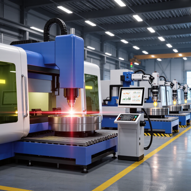
Laser Quenching Fundamentals: Process Principles and Typical Applications
Laser quenching heats a narrow surface zone above the steel’s austenitizing temperature, then relies on the cooler core to remove heat rapidly. The result is a hardened martensitic layer without a liquid quench bath. It is precise. But it is not magic: steel chemistry, surface condition, beam speed, and overlap all affect hardness and distortion. Typical hardened depths are roughly 0.2–1.5 mm, though part geometry and process settings can shift that range. ASM Handbook, Volume 4A, explains the transformation and heat-treatment controls behind this process.
In production, a moving laser spot traces gears, shafts, and cam profiles; overlapping passes help avoid soft gaps. Temperature monitoring can improve repeatability, especially around corners, where heat builds up. A 2023 MarketsandMarkets report valued the broader laser-processing market at about USD 20.2 billion, reflecting wider industrial adoption, not laser quenching alone. That distinction matters. Laser hardening works best on alloys with sufficient carbon, and it may not suit every component or repair. A small trial section is often more revealing than a confident simulation. Some process settings still need adjustment on the actual part.
Key Machine Metrics: Laser Power (kW), Scan Speed (mm/s), and Case Depth (mm)
Laser power, scan speed, and case depth are useful starting points when comparing laser quenching machines. They are not interchangeable performance guarantees. Power, stated in kilowatts, describes available output, but the delivered energy also depends on beam focus, spot size, and surface condition.
More power is not automatically better. Excess heat can distort a thin edge or create an uneven hardened zone.
Scan speed, measured in millimeters per second, affects how long each area receives energy. A faster pass may reduce heat input, while a slower pass can deepen treatment; the result depends on the material and setup.
Numbers need context. Ask whether the quoted speed was tested on the same alloy, component shape, and optical arrangement you use.
Case depth, measured in millimeters, should be verified on representative parts, ideally through documented cross-section testing. A polished sample under magnification can reveal a shallow or irregular layer that a machine display cannot.
Small differences matter. It is easy to compare headline specifications and miss repeatability, measurement methods, or edge-to-edge variation.
Even a well-documented test may not predict every production part, so trial runs remain important.
Top 10 Laser Quenching Machine Manufacturers Worldwide: Company Profiles
A reliable Top 10 Laser Quenching Machine Manufacturers Worldwide feature should make each company profile useful, not merely promotional. Compare manufacturers by machine configuration, laser power range, motion-system accuracy, and available process monitoring. Ask whether stated performance comes from published specifications, customer trials, or a specific test setup. These details matter. A system designed for small gears may not suit large shafts or irregular components.
Strong profiles also explain practical support: installation, operator training, spare-part availability, and access to process engineers. Look for examples involving recognizable part shapes, such as a narrow bearing race or a toothed steel shaft. Note the material grade, treated area, and hardness measurement method when disclosed. Not every supplier publishes comparable data, so an exact ranking can suggest more certainty than the evidence allows. That is worth questioning.
Tips: Request a sample-treatment report before comparing quotes. Check the treated depth and hardness uniformity, not just peak hardness. Confirm the workpiece size and cooling arrangement used in demonstrations. A factory visit can reveal cable routing, guarding, and maintenance access. Small omissions count. A polished brochure cannot replace a measured trial on your own component.
How to Compare Manufacturers: Automation, Part Size, and Process Capability
When comparing laser quenching machine manufacturers, look beyond advertised power and cycle speed. Ask how each system handles your actual part geometry, material, and required hardened depth. A shaft with shoulders needs different beam movement and fixturing than a flat plate. Request sample results from comparable parts, including hardness readings and case-depth measurements. Small details matter.
Automation should match your production, not just look impressive. Check whether loading, part rotation, recipe changes, and inspection can be integrated smoothly. For large or irregular components, confirm the working envelope and maximum part weight in writing. Ask about beam control, temperature monitoring, and how the system responds when a part varies slightly between batches. A polished demonstration may hide setup time. It is worth asking to see a full changeover.
Tips: Bring drawings and process targets to supplier discussions. Compare cycle time, repeatability, maintenance access, and operator training. Request a clear list of assumptions behind each quoted capability. If possible, run a trial using your own material; published specifications cannot reveal every production wrinkle.
Top 10 Laser Quenching Machine Manufacturers Worldwide
How to Compare Manufacturers: Automation, Part Size, and Process Capability
The bars count practical items to verify when comparing suppliers—not manufacturer ratings or rankings. Check automation integration, the machine’s working envelope and load limits, and process controls such as laser power, beam or spot adjustment, scan speed, and monitoring. Confirm each specification against your parts and application.
Quality Verification: ISO 18203:2016 Case-Depth and ISO 6507-1 Vickers Tests
For a laser-quenching machine, a bright surface is not proof of a sound hardened layer. Quality checks should connect the process to measurable results. ISO 18203:2016 provides methods for determining the thickness of surface-hardened layers in steel. The inspection plan should define the relevant depth, sampling location, and acceptance limit before testing. Do not assume one hardness cutoff suits every steel grade or component.
A typical check uses a cut cross-section, carefully mounted and polished to reveal the layer. A Vickers hardness traverse under ISO 6507-1 can map hardness from the surface into the softer core. Small details matter. Indent spacing, test force, surface preparation, and instrument verification can affect the profile. Record each position and reading, then compare the results with the agreed depth definition. A single section may miss variation across a part, especially near edges or curved surfaces. I would not treat one reading as proof. Repeat measurements at representative locations, and retain the raw data, calibration records, and section images. The method is disciplined, but not flawless: preparation artifacts or uneven laser heating can complicate interpretation. Keep records.
Top 10 Laser Quenching Machine Manufacturers Worldwide — Quality Verification: ISO 18203:2016 Case-Depth and ISO 6507-1 Vickers Tests
Independent comparison framework. Company names, brands, vendor rankings, and supplier-specific performance claims are intentionally omitted. Acceptance limits should be set by the part drawing, application, and agreed test plan.
| No. | Evaluation Dimension | What to Verify | Evidence or Test Method | Comparison Criterion |
|---|---|---|---|---|
| 1 | Hardened-layer depth | Depth and consistency of the laser-hardened layer on representative production parts. | ISO 18203:2016 provides methods for determining the thickness of surface-hardened layers in steel. Record the method and section location used. | Compare measured results with the part drawing or agreed process specification; there is no single universal case-depth limit. |
| 2 | Vickers hardness | Hardness profile from the treated surface into the unaffected substrate. | ISO 6507-1 specifies the Vickers hardness test method. Document test force, indenter, dwell time, surface preparation, and measurement locations. | Check that the specified hardness range and profile are achieved at the locations and test conditions agreed for the component. |
| 3 | Hardness-profile repeatability | Variation in hardness and hardened-layer depth across repeated parts and defined locations. | Use a documented sampling plan and repeated cross-section measurements on representative parts or coupons. | Compare variation against customer-defined tolerances and the agreed production acceptance plan. |
| 4 | Laser power control | Ability to set, monitor, and record laser output during the treatment cycle. | Review calibration records, power-monitoring data, alarms, and process logs for the trial and production runs. | Verify that the control and recording capability meets the process-monitoring requirements; allowable deviation must be specified for the application. |
| 5 | Beam and scan control | Control of the treatment path, scan speed, beam position, and overlap where applicable. | Review the programmed path, parameter records, and trial-piece inspection results for the required geometry. | Confirm that the system can reproduce the approved path and process window on the actual component geometry. |
| 6 | Geometry and access | Coverage of the specified surfaces, including curved, narrow, or obstructed features. | Conduct a representative-part trial and inspect treated locations against the component drawing and agreed inspection plan. | Assess coverage, edge effects, and untreated zones against part-specific requirements rather than a generic capability claim. |
| 7 | Thermal and metallurgical results | Evidence that the treatment achieves the required hardened structure without unacceptable cracking or distortion. | Use agreed metallographic examination and dimensional inspection on representative trial parts; define sampling and acceptance criteria in advance. | Evaluate results against the material specification, drawing requirements, and customer-approved process qualification plan. |
| 8 | Workholding and automation | Repeatable part location and integration with loading, unloading, and any required rotation or motion axes. | Review fixture design, positioning repeatability data, cycle sequence, and a production-representative run. | Confirm that workholding and motion support the required access, takt time, and process repeatability for the application. |
| 9 | Safety and interlocks | Protection appropriate to the laser system and installation, including enclosure, access control, and interlock functions. | Review the machine risk assessment, safety documentation, interlock checks, and applicable local regulatory requirements. | Verify compliance for the intended installation and operating environment; requirements depend on system design and jurisdiction. |
| 10 | Quality records and support | Traceability of recipes, calibration, maintenance, inspection results, and process changes. | Review sample production records, operating and maintenance documentation, training provisions, and change-control procedures. | Compare documentation and support arrangements with the buyer’s quality system, traceability needs, and service expectations. |