
Blog
7 Tips for Choosing the Right Stocko Connector
Choosing the right Stocko Connector is rarely a simple catalog decision. The correct part must fit the wire, housing, current load, assembly method, and operating environment. A connector may look suitable on a workbench. Heat, vibration, moisture, and repeated insertion can reveal weaknesses later.
Reliability expert Dr. Michael Pecht offers a useful principle: “Reliability must be designed in, not inspected in.” This idea applies directly to every Stocko Connector selection. The guide examines terminal size, contact material, insulation, locking design, wire compatibility, and installation conditions. It also considers supplier documentation and long-term availability. Small details matter. A loose crimp can create heat. A poor seal can invite corrosion. An unsuitable plastic may become brittle near a motor or heater.
Experience still has limits. Product drawings can be misunderstood, and real assemblies sometimes behave differently. That is why sample testing, pull-force checks, and visual inspection remain important. Do not trust appearance alone. A connector that clicks firmly may still have an incomplete crimp.
These seven practical tips are designed for engineers, purchasing teams, and maintenance professionals. They encourage careful comparison before production begins. The goal is not merely to find a connector that fits today. It is to choose a Stocko Connector that remains stable, serviceable, and traceable throughout its working life. Some projects will need a second review. That is not failure. It is responsible engineering.
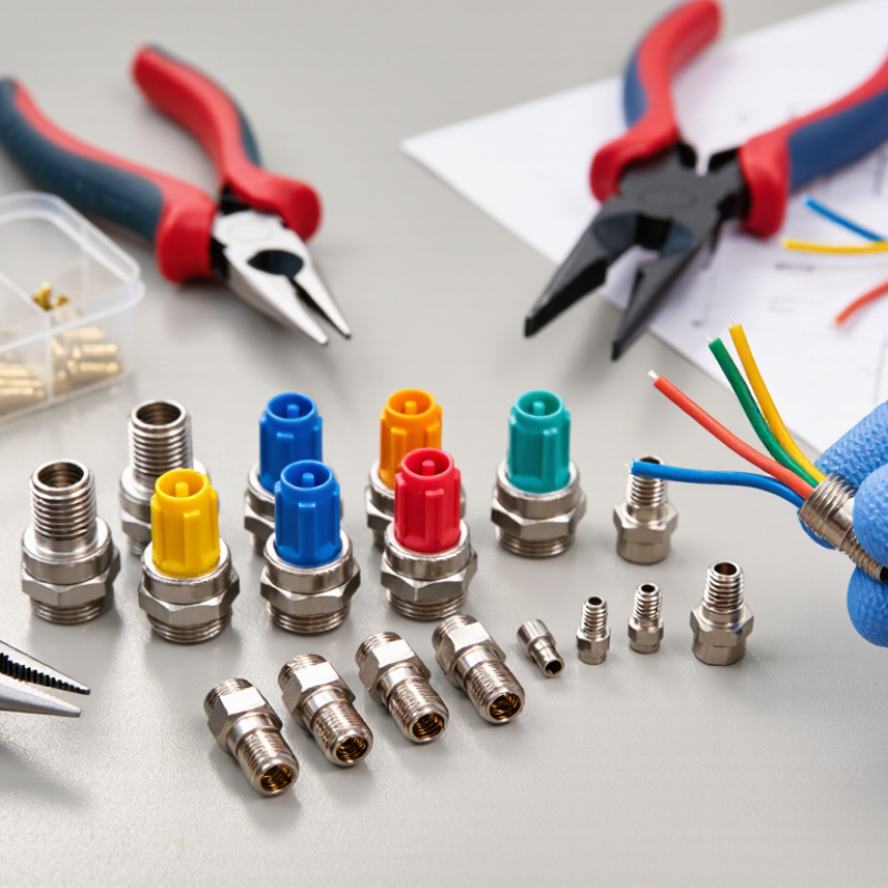
Identify the Connector’s Application and Environmental Requirements
A connector should be selected from its working conditions, not its catalogue appearance. In field installations, vibration, moisture, heat, and repeated mating often cause more failures than electrical overload. Record the current, voltage, wire size, mating cycles, and available space before comparing options. A connector inside a control cabinet faces different risks from one near an engine or outdoor enclosure. Small details matter.
Check temperature ranges during real operation, including startup and shutdown. Use IEC 60529 ratings to assess protection against dust and water, but do not treat an IP rating as a complete solution. Condensation, chemical vapors, and cable movement still require separate evaluation. A 2024 report from the International Telecommunication Union and UNITAR states that global electronic waste reached 62 million tonnes in 2022. Better environmental decisions can reduce premature replacement, although connector selection alone cannot solve that problem.
Test the connector with the actual cable and housing. Pull it gently. Twist it repeatedly. Inspect contact resistance after vibration and humidity exposure. ISO 16750 provides useful environmental test guidance for road vehicles, while IEC 60512 supports connector testing methods. These standards improve confidence, but laboratory results may not match a dusty workshop or a poorly routed cable. I have seen attractive assemblies fail because moisture had nowhere to escape. That is an uncomfortable lesson. Choose the connector’s application first, then verify its environmental limits with evidence.
Check Electrical Ratings, Contact Layout, and Connector Compatibility
Choosing the right connector starts with its electrical ratings, not its appearance. Check the rated voltage, continuous current, and peak current for your actual application. A connector carrying six amps in a cool test room may perform differently inside a warm enclosure. Allow headroom. Heat accelerates contact wear and can soften nearby insulation.
Tip 1: Verify every rating against operating conditions. Review temperature derating, wire size, insulation class, and expected duty cycle. Do not rely on a single headline value. A datasheet can look complete, yet small footnotes may change the selection.
Tip 2: Study the contact layout carefully. Count the contacts, measure their pitch, and confirm the numbering direction. Check keying, polarity, and the cable exit angle. A plug can fit physically and still connect the wrong circuits. Small errors matter. Use the mechanical drawing before ordering samples.
Tip 3: Confirm connector compatibility beyond mating shape. Check the matching half, terminal type, locking method, mounting space, and approved wire range. Examine strain relief as well. During practical testing, gently pull the cable and inspect whether the terminals shift. Then measure voltage drop under load. It is a simple check, but it catches weak contact pressure. I have found that bench tests can be too forgiving. Vibration, dust, repeated mating, and temperature changes may expose problems later. Record these conditions and test again before approving the design.
Select the Suitable Housing, Termination, and Mounting Style
Choosing the correct connector starts with the housing. It must match the wire size, contact count, insulation thickness, and required protection level. A compact housing saves space, but it may leave little room for finger access during assembly. Check the locking feature carefully. A clear click helps technicians confirm engagement without pulling the wires repeatedly.
Termination style affects both reliability and production speed. Crimp contacts usually provide consistent results when the tool, terminal, and conductor size match. Solder terminations can suit prototypes, but they demand controlled heating and careful inspection. Avoid judging a contact by appearance alone. Measure pull strength, inspect the crimp profile, and test the connection after vibration or temperature cycling. Small errors often hide beneath acceptable-looking work.
Mounting style should reflect the real panel and service conditions. Through-hole mounting offers strong mechanical support, while snap-in mounting can reduce installation time. PCB spacing, panel thickness, cable direction, and access for maintenance all matter. Test a sample in the actual enclosure, not only on a workbench. That step has prevented many avoidable redesigns. I have also learned that a connector chosen for easy assembly may complicate later repairs. Leave enough clearance for tools and hands. Verify polarity, retention force, and strain relief before approving the design. Datasheets guide the decision, but practical testing earns confidence.
| No. | Selection Dimension | Available Options | Recommended Selection Guidance | Key Technical Considerations |
|---|---|---|---|---|
| 1 | Housing Material |
| Use an insulating thermoplastic housing for most indoor electrical assemblies. Consider a reinforced or metal housing where higher mechanical strength, heat resistance, or shielding is required. | Check operating temperature, flammability rating, chemical exposure, impact resistance, and insulation requirements before finalizing the housing. |
| 2 | Number of Circuits |
| Select the smallest circuit count that accommodates the required power, signal, and spare positions. A modular or multi-position housing can reduce wiring space and assembly time. | Allow additional space for creepage, clearance, wire routing, and future circuit expansion. Do not exceed the connector’s approved pole configuration. |
| 3 | Pitch and Contact Spacing |
| Choose a fine pitch when PCB or enclosure space is limited. Select a wider pitch when larger wire sizes, higher current, better heat dissipation, or easier manual assembly are needed. | Smaller spacing generally requires greater control of insulation stripping, insertion accuracy, creepage, and clearance. Confirm compatibility with the mating half. |
| 4 | Termination Method |
| Use crimp contacts for repeatable wire harness production and vibration-prone applications. Use solder termination for low-volume assemblies or applications where soldering equipment is already available. Use PCB tails for direct board mounting. | Verify conductor cross-section, insulation diameter, contact plating, tooling requirements, pull-out strength, and the approved termination procedure. |
| 5 | Mounting Style |
| Choose free-hanging connectors for harness-to-harness connections. Select panel mounting for equipment interfaces, PCB mounting for board-level connections, and locking hardware when vibration or repeated service is expected. | Check panel cutout dimensions, PCB hole pattern, retention force, mounting orientation, cable strain relief, and available installation clearance. |
| 6 | Electrical Rating |
| Choose contacts whose rated voltage and current exceed the actual continuous load. For mixed circuits, separate high-current and signal contacts where the connector system permits it. | Ratings depend on contact size, wire size, ambient temperature, number of energized positions, and derating conditions. Use the applicable product specification rather than relying only on nominal values. |
| 7 | Retention, Polarization, and Environment |
| Use a keyed, polarized, and positively locking design where incorrect mating, accidental disconnection, vibration, dust, or moisture could affect system reliability. | Evaluate ingress protection, sealing method, temperature cycling, vibration, shock, mating-cycle life, and the need for secondary locks or strain relief. |
Evaluate Materials, Durability, Safety, and Regulatory Compliance
7 Tips for Choosing the Right Stocko Connector
Material selection should match the working environment, not just the purchase price. Check housing materials against heat, moisture, chemicals, and ultraviolet exposure. Select contact metals that resist corrosion and maintain stable conductivity. I have learned that a connector can look excellent during inspection yet fail after repeated thermal cycling.
Review durability through mating cycles, vibration, pull force, and cable movement. Ask for test results, not broad promises. Examine the locking system with gloved hands. It should engage clearly and resist accidental release. Sealing matters too. Confirm the protection rating under realistic installation conditions, including dust, splash, and cable bending. Small details often decide service life.
Safety requires more than insulation thickness. Check voltage, current, creepage, clearance, temperature rise, and touch protection. Verify compatibility with applicable international and regional standards. Request declarations, test reports, traceability records, and production quality controls. Documentation should identify the tested configuration, not merely the connector family. Do not overlook assembly tools and training. Poor crimping can undermine a well-designed component. A checklist helps, but it is not perfect. Field conditions may expose weaknesses that laboratory tests miss. Use samples in the actual enclosure, then inspect them after installation and environmental testing.
Compare Installation Needs, Availability, and Total Ownership Cost
7 Tips for Choosing the Right Stocko Connector
Compare Installation Needs, Availability, and Total Ownership Cost
Tip 1: Map the installation space before comparing connector prices. Measure clearance, cable bend radius, mating direction, and tool access. Tip 2: Match the connector to heat, vibration, moisture, and cleaning chemicals. A laboratory rating may fail on a factory floor. Tip 3: Estimate labor minutes, not just component cost. A connector requiring awkward crimping can quietly increase production expense.
Tip 4: Check current stock, regional warehouses, and realistic lead times. McKinsey’s 2020 supply-chain survey found that 93% of leaders pursued resilience improvements after major disruptions. Availability deserves engineering attention. Tip 5: Confirm approved alternatives and terminal compatibility before production starts. One substitute may fit mechanically but fail electrically. Test it.
Tip 6: Calculate total ownership cost over the product’s service life. Include tooling, inspection, replacement labor, downtime, inventory, and warranty exposure. The U.S. Department of Energy reports that motor systems consume about 23% of American electricity, so connector reliability can influence broader equipment losses. The connector itself may use no power, but a loose contact can stop a powered system.
Tip 7: Validate samples under real assembly conditions. Record insertion force, pull strength, contact resistance, and rework time. Field audits often expose assumptions that spreadsheets miss. A low unit price can still mislead. Review the decision after pilot production, because the first estimate is rarely perfect.