
Blog
What Is a Crawler Final Drive and How Does It Work?
A crawler can push through wet clay, broken rock, and steep ground, but its travel system takes repeated shock loads. At each track, the Crawler Final Drive converts hydraulic motor output into slower, higher-torque rotation. That reduction turns the sprocket and moves the machine. The assembly is compact, but it carries substantial mechanical work.
Industry reports help explain why this component matters, though they require careful reading. Off-Highway Research’s global construction-equipment market reports track machine sales and regional demand. Association of Equipment Manufacturers (AEM) shipment data provide another view of equipment activity. These sources describe the market, not final-drive failure rates. That distinction matters. Sales figures cannot tell an owner how long a specific drive will last.
Inside the housing, planetary gears multiply torque while reducing rotational speed. Bearings support the rotating parts, and seals retain lubricating oil against dirt and water. In the field, a damaged seal may leave a thin oil trace near the sprocket. A low oil level can then accelerate gear or bearing wear. Still, one symptom is not a diagnosis. Oil condition, operating hours, track tension, and machine model all shape the evidence. This guide explains the parts, power path, and common warning signs, while noting where inspection or the manufacturer’s service manual should guide the next step. Real conditions vary. That is easy to overlook.
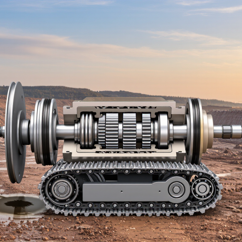
Crawler Final Drive: The Hydraulic-to-Track Power Path
What Is a Crawler Final Drive and How Does It Work?
Crawler Final Drive: The Hydraulic-to-Track Power Path
A crawler final drive turns hydraulic flow into track movement. The pump sends pressurized oil through control valves to a hydraulic travel motor. Inside the motor, rotating components convert fluid pressure into torque. A compact planetary gear set then multiplies that torque and reduces speed. The output turns the sprocket, pulling the track around its rollers. Slow, forceful motion is the goal.
The pressure path matters. A kinked hose, leaking seal, or restricted filter can reduce flow and weaken travel. Heat offers a useful clue: an unusually hot final-drive housing may point to excess friction, poor lubrication, or internal leakage. It is not a diagnosis by itself. Check both sides of the machine, since uneven travel can also come from track tension or valve problems.
Fluid condition matters too. ISO 4406:2021 classifies hydraulic-fluid contamination by particle counts; its codes are not cleanliness percentages. That distinction is easy to miss. SAE technical guidance on hydraulic systems likewise treats contamination control as essential to component life. In service, record oil condition, case-drain flow, and operating temperature before replacing parts. Small samples and readings can reveal a developing problem, though field measurements are imperfect and should be compared with the machine’s service specifications.
Hydraulic Motor Operation at Typical Excavator Pressures of 300–350 bar
A crawler final drive converts hydraulic power into slow, high-torque track rotation. Its hydraulic motor receives pressurized oil, then drives a planetary gear set that reduces speed and multiplies torque. Excavator pressures of 300–350 bar equal 30–35 MPa. That is substantial force. For scale, an ideal 100 cm³/rev motor at this pressure produces roughly 477–557 N·m before mechanical losses. Actual output varies with motor design, oil temperature, and internal leakage.
Pressure alone does not determine track speed: oil flow matters too. ISO 4409:2019 sets standardized methods for measuring and presenting steady-state performance of hydraulic pumps and motors, including flow, torque, and efficiency. In field checks, compare pressure and flow with the machine’s service specifications; a normal pressure reading can hide weak flow or excessive leakage. Look for oil leaks around the final-drive housing, unusual heat, and metallic particles in drained oil. Small details matter. Cleanliness matters as well. The range here is a typical reference, not a universal setting, and I would not diagnose a drive from pressure alone.
| Component or operating factor | What it does | How it works in the final drive | Typical facts and considerations |
|---|---|---|---|
| Hydraulic supply | Delivers pressurized oil from the excavator’s hydraulic system. | Control valves direct oil to the travel motor to move the selected track forward or backward. | Operating pressures of 300–350 bar equal 30–35 MPa. Actual pressure depends on machine design, load, and operating conditions. |
| Hydraulic travel motor | Converts hydraulic energy into rotary motion. | Pressure difference across the motor moves its internal rotating group; reversing oil flow reverses motor rotation. | Axial-piston motors are commonly used in excavator travel drives. Motor speed depends mainly on oil flow and motor displacement. |
| Motor torque | Provides the rotational force needed to drive the track. | Motor torque increases with pressure difference and motor displacement. A simplified relationship is torque ≈ pressure difference × displacement ÷ 2π, adjusted for mechanical efficiency. | Pressure alone does not determine output torque; displacement, efficiency, and losses also matter. |
| Planetary reduction gears | Reduce motor speed and multiply torque. | One or more planetary gear stages transfer motor rotation to the output while providing a compact, high-ratio reduction. | The reduction ratio is designed for the machine’s travel-speed and tractive-force requirements; it varies by drive design. |
| Final-drive housing | Supports and protects the motor and reduction gears. | The sealed housing contains lubricating oil for the gears and bearings and helps keep contaminants out. | Gear lubrication is separate from the motor’s hydraulic oil circuit in many designs. Check the machine’s service instructions for the correct oil and level. |
| Output hub and drive sprocket | Transfer reduced rotation to the crawler track. | The final-drive output turns the sprocket, whose teeth engage the track links and pull the track around the undercarriage. | Sprocket and track-link wear can affect engagement and contribute to uneven or noisy travel. |
| Case-drain circuit | Returns internal leakage oil from the motor to the hydraulic system reservoir. | A dedicated drain line helps prevent excess pressure from building inside the motor case. | Restricted or incorrectly connected case-drain plumbing can cause motor damage. Permitted case pressure and drain flow are model-specific. |
| Travel speed and direction | Control how quickly and which way the track moves. | Oil flow to the motor influences speed; changing the direction of flow reverses rotation. Some drives include a selectable displacement or speed range. | Available speed ranges and control methods vary. The travel control, hydraulic flow, machine load, and terrain all affect actual speed. |
| Pressure relief and overload protection | Help limit pressure spikes and protect hydraulic components. | Relief or cross-port protection may direct oil when pressure exceeds a designed limit, depending on the hydraulic circuit. | Protection settings are machine-specific. Do not assume the typical 300–350 bar operating range is the correct relief-valve setting. |
| Inspection and maintenance | Help maintain reliable travel and identify problems early. | Technicians check for leaks, unusual noise, excess heat, abnormal case-drain flow, and correct gear-oil condition. | Use the machine manufacturer’s service specifications for pressure tests, fluid selection, oil level, and replacement intervals. |
| Note: Pressure, motor displacement, gear ratio, flow, torque, and service limits vary among excavator models. Values and procedures should be confirmed in the applicable machine and component service documentation. | |||
Planetary Gears: How Speed Reduction Increases Track Torque
What Is a Crawler Final Drive and How Does It Work?
Planetary Gears: How Speed Reduction Increases Track Torque
A crawler final drive uses planetary gears to slow motor rotation and increase torque at the track sprocket. Typically, the sun gear drives several planet gears inside a ring gear. Their combined motion turns the carrier and sprocket. More reduction means more torque, though the track moves more slowly. Small gears. Big leverage.
For example, 300 Nm of motor torque through a 40:1 reduction at 95% efficiency produces about 11,400 Nm at the output. This is an illustrative calculation, not a machine rating. The U.S. Department of Energy’s 2014 Improving Motor and Drive System Performance sourcebook uses roughly 95% as a practical benchmark for efficient gear reduction. Actual final-drive efficiency varies with lubrication, load, temperature, and wear. The figure can mislead if losses or shock loads are ignored.
Tips: Check the manufacturer’s service specifications for oil grade and change intervals. Look for leaks, unusual heat, or metallic debris in the oil. A quiet drive can still be worn.
As the planetary gear reduction ratio increases, output speed decreases while track-side torque increases. This illustration assumes a constant input of 100 N·m at 1,800 rpm and 90% drive efficiency; actual final-drive performance varies by design and operating conditions.
Final-Drive Output: Turning Torque into Sprocket Rotation and Track Motion
A crawler final drive receives low-speed, high-torque power from the transmission and reduces speed further at the track sprocket. Inside, planetary gears share the load while multiplying torque. The sprocket’s teeth engage the track links, pulling the track around the rollers and moving the machine. Simple in principle. Not gentle in practice.
Consider an illustrative calculation, not a test result: at 100 kW and 1,800 rpm, input torque is about 531 N·m. A 40:1 reduction at an assumed 90% efficiency produces roughly 19,100 N·m at 45 rpm. With a 0.3-m sprocket radius, that corresponds to about 1.06 m/s of track speed before slip. Actual output changes with oil temperature, wear, load, and track conditions. ISO 6336-1:2019 sets out methods for calculating gear load capacity; it is a useful engineering reference, not a guarantee of field performance.
At the machine, torque becomes track motion only when the sprocket can push against the track and ground. Mud can soak up the difference. A worn sprocket may climb or strike the track links instead of driving them cleanly, adding noise and shock loads. A technician can check tooth profiles, oil condition, leaks, and unusual casing heat. Heat matters. One awkward detail: a machine may still travel while a failing bearing or gear is quietly worsening.
Key Performance Data: Rated Torque, Gear Ratio, Speed, and OEM Limits
A crawler final drive is the reduction gearbox at each track. It converts motor speed into high sprocket torque. Four figures matter: rated torque, gear ratio, output speed, and allowable operating limits. Rated torque must be checked at the specified shaft and duty cycle; an input rating is not an output rating.
Gear ratio links speed and torque. In a simplified example, 1,800 rpm entering an 80:1 reducer produces about 22.5 rpm at the output. At 90 percent efficiency, 12,000 Nm input torque gives roughly 864,000 Nm output torque. These are illustrative calculations, not typical equipment specifications. Real torque fluctuates during turns, track impacts, and digging. Small details matter.
For engineering checks, ISO 6336-1:2019 describes methods for assessing cylindrical gear load capacity, while ISO 281:2007 addresses rolling-bearing life calculations. Neither standard supplies one universal crawler-drive rating. Compare the stated torque and speed with the machine’s operating limits, including peak load, oil temperature, and duty cycle. Those limits may be lower than a simple ratio calculation suggests. That shortcut is useful, but incomplete. OEM documentation should define the permitted input speed, shock loading, and continuous torque; exceeding any limit can shorten gear or bearing life.