
Blog

How to Choose the Best Illuminated Tact Switch in 2026?

Choosing the best Illuminated Tact Switch in 2026 starts with the job it must perform. Will it sit behind a compact control panel, on a handheld instrument, or near a machine exposed to dust? Each setting changes what matters. A bright LED may look clear in a showroom but cause glare in a dim room. A low-profile actuator can save space, yet feel awkward with gloves. Small details matter.

Check the switch’s operating force, travel, electrical ratings, LED color, and mounting dimensions against the device design. Confirm the panel cutout and terminal layout before ordering samples; a few millimeters can create costly rework. Review the manufacturer’s datasheet for operating life and environmental limits, then test representative units under realistic conditions. Include viewing angle and light uniformity in that test. The indicator should remain visible without washing out nearby labels.

There is no universal best choice. It depends on the user, enclosure, and expected duty cycle. In design reviews, teams can focus too much on appearance and overlook tactile feedback. That is easy to miss. Compare documented specifications, request technical support when details are unclear, and verify performance in the actual assembly. Even a careful selection can need revision after hands-on testing. That is not failure; it is useful evidence.
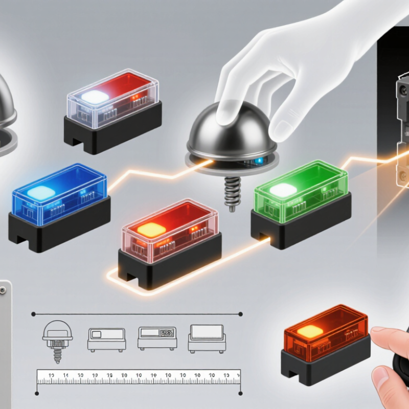
How to Choose the Best Illuminated Tact Switch in 2026?

What an Illuminated Tact Switch Is and How It Works

An illuminated tact switch combines a momentary mechanical switch with a small light source, usually an LED. Pressing its cap moves a spring dome until it touches the circuit contacts, briefly completing the switch circuit. Release the cap, and the dome returns; the contact opens. The LED has its own terminals and may be wired to light continuously or only when the device is powered. A soft click. The exact feel and travel depend on the switch’s construction, so check its datasheet rather than judging by appearance.

The U.S. Department of Energy’s LED Lighting Factsheet reports that LEDs use at least 75% less energy and can last up to 25 times longer than incandescent lighting. That comparison describes lighting generally, not tact-switch indicators; still, it highlights why LED efficiency and operating life matter in compact controls. Check LED forward voltage, current, switch rating, actuator height, and mounting dimensions. A mismatch can mean a dim indicator, excess heat, or a switch that does not fit the panel. Small details matter here.

Tips: Confirm whether the LED and switch contacts are electrically independent, then test the part at its intended voltage. Also check brightness in the actual enclosure; a clear lens can look surprisingly harsh in a dark room.

Which Electrical and Mechanical Requirements to Define

Before selecting an illuminated tact switch, define its electrical conditions. Record the supply voltage and the LED’s forward voltage and current. Check whether the light needs a separate resistor or driver. Then confirm the contact rating for the actual load, not just a resistive test load. Motors and lamps can create brief current spikes. Small details matter.

Mechanical requirements should match the panel and the user’s hand. Measure panel thickness, mounting-hole diameter, and the clearance behind the switch. Specify actuator travel and operating force; a button that feels crisp on a bench may feel tiring in repeated use. Also consider vibration, dust or moisture exposure, operating temperature, and expected press cycles. These details shape both the housing and the test plan.

Ask how the switch will be assembled: through-hole or surface mounting, hand soldering or reflow. Check the LED’s color and brightness under the intended ambient light, since a vivid indicator in a dark room may disappear beside a sunny window. In practical evaluations, a paper specification alone can miss awkward finger access or glare. Test it early. Build a small panel mock-up and operate it with the real wiring and enclosure. A first prototype may still reveal a requirement you forgot to define.

How to Compare LED Colors, Brightness, and Lighting Styles

LED color should match the signal’s meaning and the surrounding panel. Red and green are easy to distinguish in many settings, but check the actual switch under the intended ambient light. Warm workshop lighting can shift how a cool blue appears. Color can fool the eye. The U.S. Department of Energy’s 2020 U.S. Lighting Market Characterization estimated that LEDs made up 48% of installed lighting in 2020, up from 4% in 2012. That broader market trend makes LED choice familiar, but it does not guarantee consistent color in a compact switch.

Compare brightness at the same rated current and viewing angle. Switch specifications often list luminous intensity in millicandelas (mcd); a higher number does not always look brighter from every direction. A narrow viewing angle can create a sharp, bright point, while a diffuser or light pipe spreads light across the cap. For a quick bench check, view samples straight on and from the side, with the panel powered at its expected voltage. Record the color and brightness. My own first impression is sometimes wrong.

Choose a lighting style that suits the task. A single illuminated spot works for simple status cues; a ring or evenly lit cap can be easier to notice at a glance. Ask for test data measured under consistent conditions. The IES LM-79 method describes electrical and photometric measurements for solid-state lighting products; it offers a useful measurement reference, though a tact switch is a different component. Compare samples in the finished panel, not just on a datasheet.

How to Choose the Best Illuminated Tact Switch in 2026?

Compare typical LED forward-voltage ranges by color. Values are approximate at 20 mA; check the switch datasheet for exact specifications.

Brightness: Compare luminous intensity in millicandelas (mcd) only when current and viewing angle are also specified. Forward voltage does not indicate brightness.

Lighting styles: Single-color suits a clear status indicator; bi-color distinguishes two states; RGB offers multiple colors but requires additional control. Choose a color, brightness, and style that remain clear in your intended environment.

How to Assess Durability, Environment, and Compliance

How to Choose the Best Illuminated Tact Switch in 2026?
How to Assess Durability, Environment, and Compliance

A switch may feel solid on the bench and fail after months of vibration. Start with the actual use case: expected presses per day, operating temperature, cleaning methods, and exposure to dust or moisture. Compare rated mechanical and electrical life separately; they measure different conditions. Ask for test methods and sample details, not just a large cycle count. Small details matter.

Check how the switch will be mounted. IEC 60529 defines enclosure protection ratings, but an IP rating for an enclosure does not automatically prove that an exposed switch is sealed. Request evidence for the assembled product under relevant conditions. For outdoor or washdown equipment, review moisture, temperature, and vibration test results. IEC 60068 provides environmental test methods. Still, a standard test cannot reproduce every real installation. I would leave some margin.

Compliance deserves the same scrutiny as durability. Confirm material declarations, traceability, and applicable market documentation with the supplier before design approval. The Global E-waste Monitor 2024 reports that 62 million tonnes of e-waste were generated worldwide in 2022, with only 22.3% documented as formally collected and recycled. That figure is not specific to switches, but it reinforces the value of components built for dependable service and repairable assemblies. Keep the evidence on file. One caveat: paperwork is only useful when it matches the exact part and revision.

How to Choose the Best Illuminated Tact Switch in 2026? - How to Assess Durability, Environment, and Compliance

Selection dimension What to assess Useful benchmarks or checks How to choose
Mechanical life Number of actuator operations before mechanical failure, and whether the rating is specified with or without an electrical load. Compare the manufacturer’s stated mechanical and electrical life separately. Tact switches may be rated from hundreds of thousands to millions of operations, depending on construction and test conditions. Choose a life rating that exceeds the estimated lifetime number of presses. Confirm the test conditions match the expected actuation and installation.
Electrical rating Rated voltage and current, load type, contact material, and switching frequency. Use the specified rating for the actual circuit. Resistive-load ratings do not automatically represent performance with capacitive, inductive, or LED-driver loads. Check inrush current and low-level switching requirements. Keep the circuit within the switch’s stated electrical limits and consider external drive circuitry where appropriate.
Operating force and travel Actuation force, pre-travel, total travel, and tactile feel. Compare the force and travel specifications with the intended user interface. Values vary by switch design and should be checked against the product’s data sheet. Prototype the switch in the actual enclosure. Panel thickness, actuator shape, and mechanical tolerances can affect feel and reliable actuation.
Operating environment Ambient temperature, humidity, condensation, dust, liquids, vibration, and shock. Check the switch’s specified operating and storage temperature ranges. These limits are product-specific; an IP rating applies only to the tested configuration and installation conditions. For exposed installations, verify the complete assembly’s ingress protection, including panel seals and mounting details. Do not assume a bare switch has the enclosure’s IP rating.
Illumination and visibility LED color, forward voltage, current, brightness, viewing angle, and visibility under ambient light. Confirm the LED’s electrical specifications and whether a current-limiting resistor or driver is required. Brightness and color can vary with drive current and operating conditions. Test the indicator through the final lens or panel in both bright and low-light conditions. Check whether the LED is separately addressable from the switch contacts.
Electrical noise and contact behavior Contact bounce, signal integrity, electromagnetic environment, and required immunity. Mechanical contacts can bounce during actuation; a suitable hardware or software debounce method may be needed. IEC 61000-4-2 defines ESD immunity test methods and levels, but the appropriate level depends on the end product. Evaluate the switch in the finished circuit and enclosure. Set ESD and EMC requirements at the equipment level rather than assuming the switch alone ensures compliance.
Materials and soldering Terminal style, PCB footprint, plating, housing materials, and compatible assembly process. Confirm the recommended soldering method and temperature profile in the data sheet. Through-hole and surface-mount parts may have different assembly constraints. Check mechanical fit, solder-joint design, and assembly tolerances before production. Avoid exceeding the specified soldering conditions.
Regulatory compliance Material restrictions, required declarations, safety approvals, and destination-market requirements. For applicable products, review current RoHS and REACH documentation. IEC or UL-related approvals and markings are specific to the component, product category, and intended use. Request current compliance documents for the exact part and verify requirements for the finished equipment and target markets. Component documentation does not replace end-product assessment.
Reliability validation Whether the component remains functional after the expected combination of use, environmental exposure, and assembly. Review test methods, sample conditions, and acceptance criteria behind published life or environmental figures. A single rating does not predict every real-world failure mode. Run application-specific tests for repeated actuation, temperature, humidity, vibration, and cleaning exposure where relevant. Validate the switch in the final mechanical and electrical design.

Note: Specifications and compliance requirements vary by part and application. Treat the benchmarks above as selection checks, and verify all ratings, test conditions, and documentation against the current data sheet and the requirements for the finished product.

How to Test and Specify a Switch for Your Application

An illuminated tact switch should be tested in the conditions it will actually face. Check the panel thickness, available PCB space, and expected finger access before choosing a part. Then measure actuation force and travel with a consistent fixture. A small fixture will not perfectly mimic a finger, but it makes comparisons repeatable. Note the switch’s feel, too.

Test electrical behavior under the intended load. Record contact resistance and switch bounce with suitable measurement equipment, and repeat the test across several samples. Check LED current and brightness at the specified supply voltage. View the indicator under realistic ambient lighting, not only in a dim lab. That detail matters. If the switch sits behind a tinted lens, test that combination as well.

Specify operating temperature, expected actuation cycles, mounting method, and acceptable force and travel ranges. Include LED color, drive conditions, and connector or soldering requirements in the drawing or procurement notes. A bench test can reveal problems, but it may miss wear or variation between production batches. Do not rely on one passing sample. Set clear acceptance limits, while recognizing that a little variation in tactile feel can be hard to describe precisely. That uncertainty deserves a note in the specification.